This project is based on
PIC24EP512GP202 microcontroller, which is 16-bit
Microchip's MCU with 512K of internal flash
program memory, 48K of internal data memory,
packed in standard 28-pin Shrink-DIP case.
The hole unit uses +5V power supply (2.1
mm coaxial CON1A or mini USB CON1B
connector, but take care not to use both!). Measured current
consumption is 77 mA. LDO regulator MCP1702-33
is used for +3.3V supplu for MCU. Some pins of
this MCU are 5V tolerant, you can check the details in the
datasheet, available
here.
Instead of quarz, you can use ceramic
resonator for the oscillator, but some of resonators will
produce significant frequency jitter, which is visible as
horizontal pixel instability on the screen. It is also possible
to use internal FRC oscillator with PLL, but, of course, the
jitter will be even worse.
R, G and B video hardware drivers are realized by
simple passive attenuators (R1R2, R4R5
and R7R8) and NPN transistors
(as emitter followers) T1-T3. There are no special
requirements for those transistors, but the low current types
(=< 100 mA) are reccomended, as the high current ones typically
have lower bandwidth. Intensity control (for "dark" colours and
gray) uses standard silicon
diodes D1-D4. Do not use Schottky diodes, as
their forward voltage drop is too low for proper dark colour
representation in analog video signal.
5-channel audio mixer uses simple
passive resistor network. Capacitor C9 is used
for passive, first order low-pass RC filter. Pull-up resistor
R14 is used in two-step volume level control
circuit. As all outputs are pure binary (on-off), low volume
level is managed by software, when the output port pins are held in
open-drain state (selectable in ODCA and
ODCB registers), as in that case resistors
R14-R20 create additional voltage
attenuator, for each output individually.
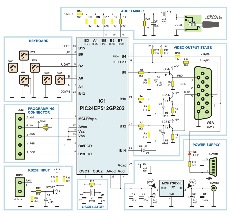
Schematic diagram v2
|
All components, including keys and
connectors, are soldered on
2-layer PCB, dimensions 50x110 mm. Here is the screenshot of the
PCB (green = bottom layer, red = top layer).
|
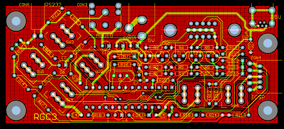
PCB v2
|
Note that PCB v2 drawing is not to
the
photo on the
intro page, e.g. arrow keys are turned
diagonaly to enable closer key positions. The photo is made with the current (v1) vesion, and
PCB drawing and the
schematic diagram on the top of this page is
new (v2) version. New PCB is ordered and will be finished at the
end of January, then I shall update the project. I hope that
there are no errors on the PCB v2 drawing, but it will be tested
only when I get the PCBs. Anyhow, you can download PCB file
(RGC3.PCB, in Protel PCB format)
here,
it is zipped together with software.
Here follows the component placement on the
PCB, mechanical details and bill of material.
 |
Bill
Of Material
ICs:
IC1 PIC24EP512GP202-I/SP
IC2 MCP1702-33
Transistors:
T1 BC547
T2
BC547
T3 BC547
T4
BC547
Diodes:
D1 1N4148
D2
1N4148
D3 1N4148
D4
1N4148
D5 1N4148
D6 LED Ø3mm
Quarz:
Q1
8MHz
Resistors
(raster 7.5 mm):
R1
1K5
R2 1K5
R3
51Ω
R4 1K5
R5
1K5
R6 51Ω
R7
1K5
R8 1K5
R9
51Ω
R10 1K5
R11 120Ω
R12 1K5
R13 120Ω
R14
1K5
R15 5K6
R16 5K6
R17
5K6
R18 5K6
R19 5K6
R20
1K5
R21 10K
R22 10K
R23
5K6
R24 5K6
R25 10K
R26
1M
R27 2K2
Capacitors:
C1 100nF ceramic
C2
4.7μF tantalum
C3 4.7μF
tantalum
C4 100nF ceramic
C5 100 nF ceramic
C6
4.7μF tantalum
C7 27pF
ceramic
C8 27pF ceramic
C9
100nF ceramic
Connectors:
Con 1A
Coaxial 2.1mm for PCB
Con 1B USB
Mini-A for PCB
Con 2
15-pin VGA for PCB
Con 3
Coaxial 3.5mm stereo for PCB
Con 4
Nylon 5-pin raster 2.54mm 90°
Con 5
Nylon 2-pin raster 2.54mm 90°
Mechanical
components:
Please see drawing |

