| Conclusion |
|
|
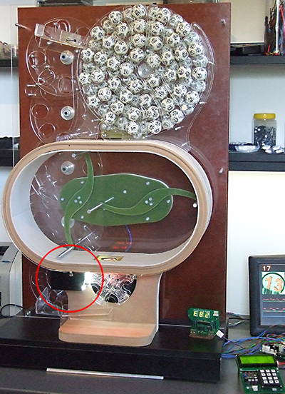
The OCR controller will be embedded in the larger project of automatic
Bingo machine, which is also under develompent. You can see the first
functional prototype here, although it is obsolete now, as I started
building the new one. The controller is in the red circle, and the small
terminal (which can also be some computer in the exploatation) is at the
bottom right. At this moment, OCR controller met all expectations. In some very rear situations (less than 1% with new balls), when the ball is positioned so that all its numbers are located far enough from the ball center on the frame, recognition is not possible and the error is reported. Same happens when the circles around the numbers are hardly damegd and broken, so my next step is to make some patch ih the algorithm, to bypass that problem. Anyway, the error is generated and reproted and there will be no false reading. Recognition rating (four-digit green number at the top row) is far above 100% in most cases, but there must be some limit of safe reading, and I think that it is about 40%. So, if the rating is below this limit, it will also generate error message. 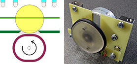 When
the error is reported, the ball should be rotated a little and the whole
process repeated. With this Bingo prototype, it is performed so that the
lower carousell (picture at the bottom) shakes CW-CCW violently for a few
degrees. All mechanical parts are driven by stepper motors (there are five
of them), so this requires no extra hardware. When
the error is reported, the ball should be rotated a little and the whole
process repeated. With this Bingo prototype, it is performed so that the
lower carousell (picture at the bottom) shakes CW-CCW violently for a few
degrees. All mechanical parts are driven by stepper motors (there are five
of them), so this requires no extra hardware.Ball transport system on my new Bingo blower will be partly different (the lower carousell is horizontal), and there will be no easy way to rotate the ball. So there will be extra repositioning set, (picture at left). The rubber cam is under the ball and, if the reading error is reported, it rotates 180° to rotate the ball slightly. At my first OCR project, I tried the neural network recognition, but I saw that the recognition itself is easy to do, so I replaced it with the much more simple algoritmic software. The main problem is not recognition itself, but proper locating and rotational angle measurement for numbers. I also noticed that it is much better to use the lens with the higher focal length, so that the bigger area of the ball is covered. That will minimize the problems with bad ball angular positioning, when all numbers on the ball are far from the image center. The main controller photo (PIC24E with assembly language, again) is also here. When I finalize my new Bingo machine, I shall place the video and project description here. And the last conclusion: I enloy doing such projects.  |
 |
 |